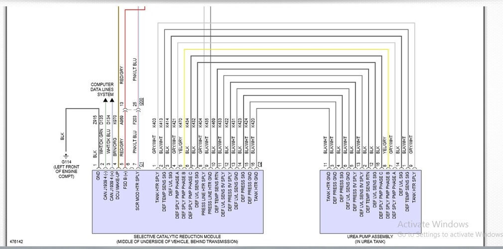
Fluid Pump Schematic
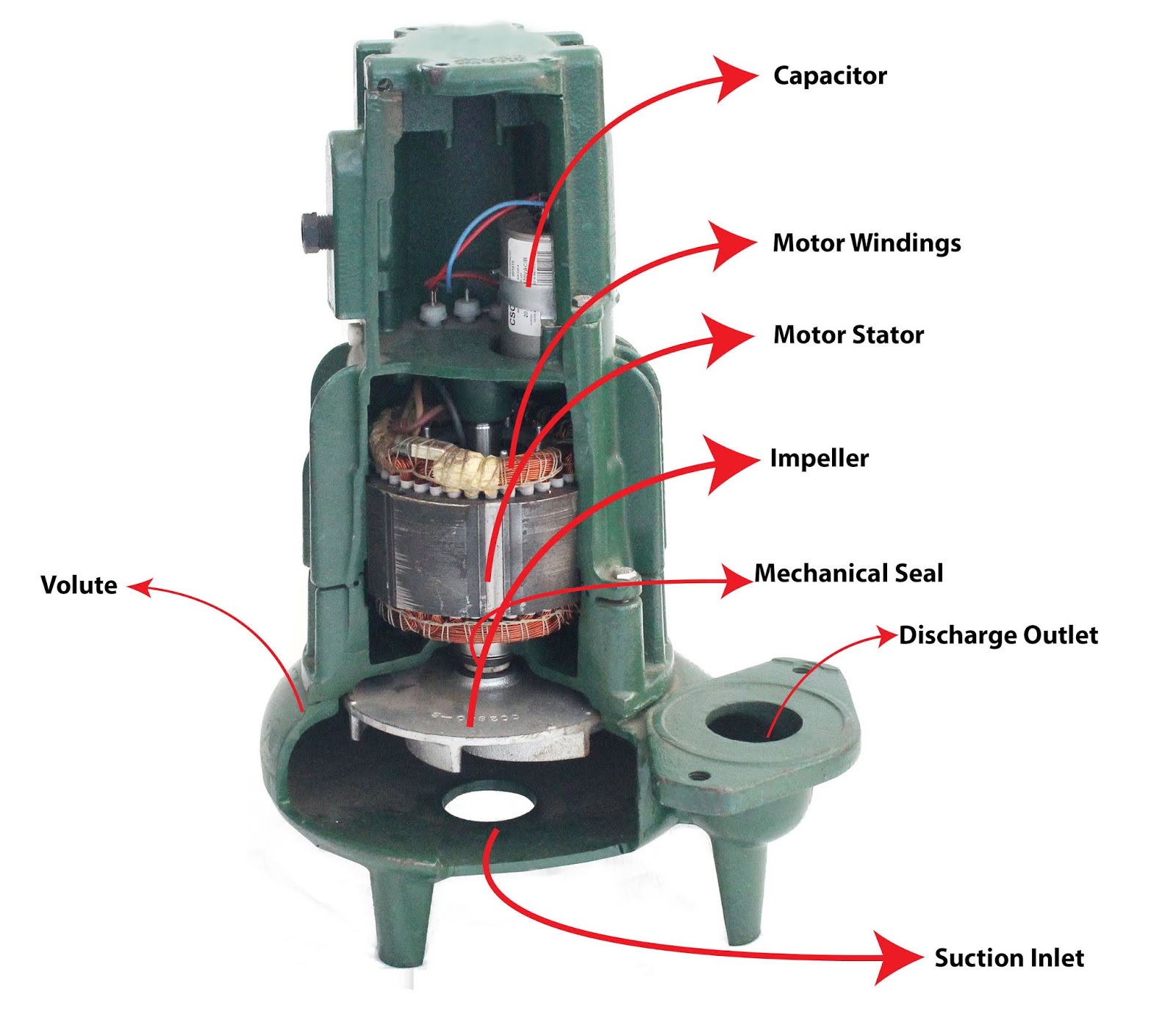
Def pump circuit Diaphragm or membrane pump working process diagram example drawing 1. main components of a centrifugal pump (taken from [47])
Heat Pumps Explained - The Engineering Mindset
Pump parts diagram cross water goulds sect Heat pumps explained Centrifugal multistage suction impeller hardhatengineer
Education safety
Submersible sump zoeller sewage pumps mengenal diagrams pumpproducts grinder liberty jenisnya sejarah adalahDef pump circuit – diagnostic network Hydraulic system fluid power motor control systems valve pressure pump directional regulator simple valves relief instrumentation components back reservoir instrumentationtoolsMengenal submersible pump: sejarah, cara kerja, dan jenisnya.
Pump partsVp44 fuel p7100 cummins corsa 12v 13a delivery governor trackbacks nov autotronik ecvv suply schematron Heat pump schematic pumps explained worksP7100 pump diagram.
![1. Main components of a centrifugal pump (Taken from [47]) | Download](https://i2.wp.com/www.researchgate.net/profile/J_Statharas/publication/336242931/figure/download/fig1/AS:810038130139136@1570139548687/Main-components-of-a-centrifugal-pump-Taken-from-47.png)
Centrifugal pump diagram
Pump sump make diagram valve check sure ready spring water airWater jet pump Centrifugal pumpCentrifugal pump parts principle working types main application advantages disadvantages its suction impeller valve foot mechanical delivery casing strainer booster.
Centrifugal fluid impeller inlet typical characteristic casing mechanics libretextsCentrifugal pump diagram How to make sure your sump pump is ready for springPump centrifugal working principle engineering lab parts manual construction diagram components details gif following.
Fluid power systems
Impeller centrifugal multistage different hardhatengineerExperiment #10: pumps – applied fluid mechanics lab manual Construction and working of centrifugal pumpDiaphragm membrane principle fluid.
Pump pumps diagram checklist suction motor tencarva safety education typical setup strainer profits improve performance use grpumpsJet schematic aufbau ksb nozzle diffuser motive handled schematischer mischrohr treibmittel fördermittel diffusor düse .


